

Advancements in production quality prototypes have evolved significantly in recent years.
Fueled by technological advances in 3D printing, optimized tooling for lower production runs, and material science, precision parts can be designed, produced, and delivered within ever-shortening time frames. The accelerating process helps reduce idle time in manufacturing cycles and enables manufacturers to move product development along and get to market faster.
Prototyping is a critical step in a product’s development that allows companies the opportunity to perfect their design before bringing products to market. However, methods of developing prototypes have spanned a broad spectrum up until recent years. From rapid 3D printing to historically slower methods that incorporate more in-depth consideration and testing of the part’s functionality and longevity, technological advancements in prototyping have made it more accessible for original equipment manufacturers (OEMs) to validate a part’s design and production strategy.
New production-quality prototyping technologies are now faster and offer better results when put into an application. Before we further define the most important considerations and process steps, let’s begin with the basics.
A plastic prototype is a three-dimensional representation of a product or object typically created using rapid prototyping technology. It can be used to test a design’s form, fit, and function before it is mass-produced. Plastic prototypes are often used in the automotive, aerospace, plumbing, medical, consumer electronics industries, and many more.
Prototyping is a powerful tool for product manufacturers as it helps assess a critical component of a physical product before full-scale production begins. A plastic prototype enables product producers to work with the physical representation of a component, and the full product, as quickly as possible to validate design intent.
This process allows design engineers to make appropriate changes before moving on to the next step of plastic component production runs and, ultimately, completing a product so it is ready to go to market. In the end, both the manufacturer and the end-product user benefit.
Other advantages include:
- Tests design features
- Verifies design intent and a plastic component’s performance in its exact end-use conditions
- Creates a testing benchmark for developing additional features
- Identifies possible defects and irregularities before mass production
- Allows refinement for further optimization and part efficiency
Engineers, mechanical designers, model makers, and tooling professionals often wonder which prototyping option is best for their plastic parts. With so many advancements in prototyping throughout the years, it can be difficult to determine which type of prototype is the best option for validating a plastic component.
It is crucial to understand the positives and negatives of each method available when you are tweaking an existing part or starting a new design from scratch. By evaluating the pros and cons of different ways to prototype plastic parts and by working with an experienced prototype partner, you will take one step closer to making the right choice.
3-D Printed Plastic Prototypes
Additive manufacturing or 3-D printing encompasses several manufacturing technologies. It is one of the innovative techniques following the cyber-physical transformation of manufacturing. While 3D printing is a blanket term, the three most popular methods for 3-D prototype plastic parts fabrication are:
Fused Deposit Modeling (FDM)
FDM 3-D printing is the most popular form in plastic prototyping, using an extrusion process to deposit plastic material layer-by-layer until the object is created. Industrial-grade FDM 3D printers can be used to manufacture plastic prototypes in high resolution and high strength. Industrial-grade FDM printers can make prototypes with greater strength and resolution depending on the materials used. It’s also a versatile method that works with various materials, including PLA, ABS, Nylon, PETG, Polycarbonate, and others.
Stereolithography (SLA)
SLA 3-D printing uses plastic resin materials for creating prototype plastic parts by utilizing a high-powered laser which helps to solidify the model using a vat of resin. An SLA 3-D printing machine uses a light source (a laser or projector) to cure liquid resin into hardened plastic. The key physical difference between SLA 3-D printers lies in configuring central components, like the light source, build platform, and resin tank. When SLA resins are exposed to certain wavelengths of light, short molecular chains join together, polymerizing monomers and oligomers into solidified rigid or flexible geometries. This process is widely used for prototyping purposes, especially in the medical, dental, and consumer goods industries.
Selective Laser Sintering (SLS)
Like SLA, SLS technology also utilizes a high-powered laser. However, what’s different about the process is it sinters powdered materials together to form a 3-D model. The advantage that this process has over others is the print quality. You will find prototype plastic parts created via this method to be more functional, with higher resolutions and greater durability and flexibility. The most commonly used material with SLS technology is Nylon (PA 11 or PA 12).
What are the pros & cons of traditional methods for 3-D printed plastic prototypes?
Pros:
- Quick production
- Allows direct upload of CAD files to 3-D printer software
- Iterations adjusted in a compressed time frame
- Cost Effective
Cons:
- Part cannot be used in functional testing
- Restricted build size
- Part may be weak and brittle
- Limitations to types of materials that can be used
- Material shrink/contraction will not be determined with 3D printing
CNC Machining
CNC machining is another somewhat quick and cost-effective approach to producing functional plastic prototypes, if a larger quantity of prototypes are needed (small volume is generally too costly). This technique utilizes a wide range of various-sized tools to carve a 3-D model out of a solid block of material. CNC machining compares favorably to 3-D printing in terms of potential for threads and undercuts, tight tolerances, reduced size limits, and more surface finish options. Turnaround times for CNC machining prototypes depend on the complexity of the model and the manufacturing service needed.
Materials used in CNC machining technology include, but are not limited to, ABS, PC, PP, POM, PMMA (Acrylic), HDPE, Teflon, and PEEK.
What are the pros & cons of CNC machining plastic prototypes?
Pros:
- Test fit, form, and function of prototype plastic parts without having to produce injection mold tooling
- Compared to 3-D prototypes, offers more significant potential for tight tolerances, undercuts, and threads
- Allows for some surface finishes on the prototype, including polishing to painting, powder coating, and more
- May allow for quick turnaround times, depending on plastic model complexity
- The prototype will offer mechanical properties closer to those of a production-quality injected part
Cons:
- Cost – machining requires large equipment with significant power and greater human oversight than 3-D printers
- For parts with complex geometries, CNC machining may be restrictive and require alternative forms of prototyping not confined by the angles of cutting tools
- More waste material is produced than other methods. Because CNC machining is a subtractive technique, it must use more material than what goes into the part. The material is cut away, and the chips end up as metal or plastic particles that must be disposed of, which is not the case with additive prototyping
Aluminum Molding Rapid Prototypes
Using aluminum for tooling can be cost-effective for low-volume injection molding. However, while it is constructed faster than steel, there are typically limitations in regard to design features, material, and quality.
Aluminum is easy to cut and has a rapid cooling rate, producing reduced cycle times and costs at the OEM level. Part production for rapid prototyping can begin almost immediately when the aluminum mold is ready.
Additionally, compared to 3D printing, rapid injection molded aluminum prototypes are produced with more accuracy and strength. However, the design and development of these parts do not always align with what is needed to bring the part through to production. Due to modification restrictions, it may be time-consuming and costly if another method is not chosen. That’s why rapid injection molding works best for an early-stage prototype but could create issues down the line if functional parts are needed.
What are the pros & cons of aluminum molded plastic prototypes?
Pros:
- Steel is a strong conductor of heat, which means it cools down and heats up quickly – ideal for injection molding
- With quick cooling, more cycles can be run at a given time for faster production than additive prototypes
- Less costly tooling investment than steel
- Functional testing is possible, but limited
Cons:
- Limitations on prototypes with unique finishes
- Not as strong as steel and lifespan is dependent on molding temperature, number of cycles, and part complexity
- Features may be left out of part due to process limitations
- Some limitations in regard to types of materials that can be used as well as texture
- Minimal engineering support
Production Prototypes
Most product manufacturers desire a plastic prototype part that can be validated for performance and mirrors the same performance characteristics of the intended final production part. If the component is used in product testing before launch, the proper finish of the intended production part should be incorporated into the prototype as well.
Production prototypes using molds made of steel are considered pre-production tools that are dimensionally accurate, incorporate all part details, and do not require de-flashing or other secondary operations. Design modifications can be made to the tool to accommodate changes or optimization. With injection molding, the part should feature even strength across each angle, and the material structure should be consistent throughout. Additionally, material finish options are limited in most layered rapid prototyping scenarios (3-D printing).
Suppose your part requires a specific finish that aids the functionality of the production part’s end use. In that case, finishing options increase greatly, and the design is not compromised when selecting an injection-molded prototype process.
Upon completion of prototyping and finalization of design, the tool is ready for production, eliminating the time needed to start the production tool-building process and qualification. Historically, lead times for production prototypes have been much longer than other methods of rapid prototyping.
Recent developments in technology and the tooling process have allowed product manufacturers to bring their concepts to reality under a dramatically accelerated time frame. When an advanced injection molding partner harnesses the latest advances in 3D printing to gain time-saving advantages over traditional prototype part testing – all aspects of the prototype process align for the most optimal outcomes.
What are the pros & cons of production-quality plastic prototypes?
Pros:
- Enables fast and cost-effective testing of product concepts without compromising quality
- A production approach is taken throughout the design and development process
- Material shrink/contraction can be planned for during the design process and inspected during development
- Widest selection of material, including abrasive/filled materials
- Most suitable for industries that need considerable testing and certifications, such as the medical products industry
- Protection of intellectual property and ability to learn from the design and part development process
Cons:
- Production prototypes use a process and mold that is typically complex and precise – often an iteration directly before the production process
- Tolerance for error is small
- Oftentimes cost may is greater upfront, but value is more significant in the long run when considering the quality, functionality, information learned throughout the process, and speed to high-volume production runs
Differences in Plastic Prototype Quality
Ultimately, the main difference between a rapid prototype and a production-quality prototype is the quality of the mold. Production-quality prototypes are made using steel molds, whereas rapid prototypes use alternative methods, most often the additive 3-D printing process or aluminum.
The use of steel in production prototypes and the inclusion of production mold features in the tooling gives engineers the opportunity to test-run the final design and material choice before high-volume production begins. This method creates cost savings and efficiencies by reducing the risk of finding flaws in the design after manufacturing millions of parts.
Fewer technologies have made an impact on product development quite like 3D printing, rapid prototyping, and production-quality prototyping. Across the world, organizations continue to discover creative uses for the technologies available to validate product components, end-use functionality, and accelerate time to market. As these technologies continue to develop, plastic prototyping will become even more efficient and further expand into industries that may have resisted in the past. The growth of new markets and industries will redefine the role of plastic prototyping and will redefine the future of product manufacturing.
There are several reasons why an OEM might need production-quality plastic prototypes. In many cases, prototypes are used to validate the design intent and proof of concept for a component or product before it goes into mass production. This can help identify any potential design issues and ensure that the component or product meets all the necessary safety and performance standards.
Below are a few scenarios when an OEM would need a production quality prototype:
- The product is intended to be mass-produced in large quantities. In this scenario, it is essential to make sure the design for manufacturing and engineering is optimized to ensure the product works as desired in its production materials.
- You need to do consumer research before mass production. You should do production quality injection-molded prototypes to produce as close as possible to the final product. Producing several hundred injection- molded prototypes allows you to do a very accurate consumer test and also provides the opportunity to make changes based on their input before mass production.
- Your product requires significant testing before it can go to market. If this is the case, you want to test a prototype that is as close to the final component as possible. The materials and production method should be identical, and if the product is complicated, it is beneficial to mimic the process and fine-tune all processes.
- Automation and assembly process of all components should be tested before going into full-scale production. If automation is built to the wrong specifications, feed systems have to be adjusted. These systems are costly and may need to be adjusted to the final specifications of each product component.
- You want to show your resellers/distributors a finished product. Customers may not make a purchasing decision based solely on a sketch or partially formed idea, so the proven prototype will help prove your product’s validity and solidify sales.
Proof of concept/design is a significant factor behind any type of prototyping. Historically rapid prototyping methods, such as 3-D printing, have helped show what a component or device might look like in terms of size and shape; however, traditional methods often don’t cut it when it comes to demonstrating whether a design concept will actually work as expected. Will the intended material stand up to all potential environmental elements and conditions? Will the chosen design be visually aligned with the product’s look? Everything from functionality to aesthetics should be considered.
Developing prototypes on a trial-and-error basis (where you send a part out for prototyping, analyze it, make changes, then repeat) is risky. The process can be tedious and costly and will likely result in a slower time to market. When qualified engineers or product design consultants are engaged in every step, they can help reduce material usage, production time, and costs associated with prototyping and development.
Let’s review the steps in creating a production-quality plastic prototype:
1. Conduct a computer-aided design (CAD) review with a detailed needs analysis.
Think specifically about how you need the plastic component to function. The importance of this step cannot be overstated because if a faulty product design is approved for manufacturing and costly tooling is developed, once the flaws are realized, you’re guaranteed to lose money and delay the product’s time to market. Questions to consider during this process include:
- Will the part be exposed to extreme temperatures? If yes, the material will need to be altered.
- What type of chemicals – if any – will the part be exposed to?
- Will the part be a visible application or an internal component?
- What does the part need to be? Flexible? Tough? Lubricated?
- Aside from temperatures, what other elements may the part be exposed to?
- Are there any sealing surfaces on the part?
2. At this stage, design for manufacturing (DFM) protocols should be instituted.
Aligning with an injection molding partner with robust DFM competencies is critical to ensure every level of detail is considered, including gate selection, side actions, cooling considerations, essential characteristics of a part, and so much more.
3. The CAD review and needs analysis, and thorough DFM implementation, will determine what tooling methods can be used to create the prototype.
Manufacturing engineers leverage the power of modern CAD software to select the proper mold needed for prototyping and, subsequently, to stand up to the rigors of production.
Some CAD programs, such as Solidworks, utilize mold simulation analysis. The technology can explore potential defects, identify potential high-stress areas that may lead to design failure, and assess how a part will operate under expected stressors. Optimizing component design without needing a physical prototype allows you to move quickly and cost-effectively through the early design process.
Rapid tooling processes use CAD methods and test findings to create molds and tools for short-production runs, product assessment, and full production. The development cycles are significantly shortened and are more cost-effective.
4. Tooling for a production-quality prototype can be completed quickly if an injection molding partner has a standardized fleet of mold bases and access to and efficiency in using 3-D printing for metal or steel molds.
Many rapid prototype producers think about how can we make this really fast? – whereas injection molders who produce production-quality prototypes will often first evaluate, how will it perform best?
New rapid prototyping methods have emerged that now allow tools to be grown from the ground up, even in high-temperature resins that withstand conventional injection molding process environments. We’ll dive into this more below.
The length of a prototyping process depends on the type of component and how it will be used. For example, plumbing, appliance, or filtration applications may take 12 – 16 weeks to test compatibility with exposure to water. It is imperative to understand if the degradation of plastic will occur when repetitively exposed to elements like water. Small engines, lawn and garden equipment, automotive and more may need to test material compatibility with exposure to oil and gas. These factors determine the timeline for producing an injection molded or production-quality prototype.
In an ideal situation, a prototyping process should only take about a month or two, with some recent advancements in the process shortening the timeframe to under 72 hours.
Preparing an initial prototype and CAD drawing for design engineers is an efficient way to make it through the process as quickly as possible. This will give engineers a clear concept of what you expect your component to look like and how you expect it to function.
Here are a few approximate plastic prototype development timelines to consider:
| Your Starting Point In The Process | What Will Get You To The Next Phase | Average Timeline |
|---|---|---|
| No design | DFM phase begins where concepts are designed or reverse engineering design is completed | One week to one month, depending on approvals |
| Design complete, but no validation | Engineers utilize mold flow analysis to make component optimizations and create a physical prototype | A few days to a few weeks, depending on the complexity of design |
| Prototype needs further optimization for production | Engineers recreate the prototype using software to improve functionality for production and intended use. Using rapid prototyping or other prototyping methods, a physical model is tested. | Using software and rapid prototyping creates efficiencies that can be completed in days or a few weeks. Traditional prototyping methods take several weeks or a few months to complete. |
| Final prototype is ready to produce | Product design determines type of mold, material, and tooling used based on quantity. Molds are created and the production process begins. | A few days to a few weeks, depending on the complexity of the design, part quantity, and assembly needs. |
In many scenarios, starting from the initial concept through the production process can take months. However, when you work with an experienced injection molder with innovative resources, the process can be significantly condensed. Below, we’ll talk about Rosti’s Innovation Lab, which helps bring concepts to reality in as few as 72 hours.
All OEMs understand that reducing time to market by any amount of time will result in many ROI benefits.
Before putting together a singular plastic component, let alone thousands or millions of them, it is essential that the engineering and design aspects of the part be carefully evaluated. The design should be technically on-point, highly functional, and aesthetically conforming to the product.
Nowadays, it’s crucial to combine these three essential components while achieving efficient production consistency. From design to function, OEMs who value delivering superior products should carefully evaluate the advantages of utilizing prototypes in injection molding processes.
Prototyping’s Vital Functions Include:
Incorporating Scientific Molding Techniques Like Mold Simulations
Rebuilding or adjusting tools is a costly process that requires time and labor. If you go into production with an unproven design, you’ll encounter a challenging situation. Mold simulations can reduce risk, as mentioned above, and should be completed before prototypes are produced.
Reduce Time to Market and Increase ROI
Prototyping is an investment, and getting a plastic component right the first time without the complete process is rare. Reevaluating and creating another iteration can be extremely expensive.
After creating a non-production prototype, you might discover small inefficiencies in the design that could make your real-time product weak, low quality, or ineffective.
Suppose you’ve manufactured hundreds or even thousands of products before recognizing errors. In that case, you know how costly it can be to scrap an entire production batch or even engage in a recall. If issues aren’t identified before the production run, time and money are lost due to adjustments in tooling.
DFM plays a pivotal role in the creation of production-quality plastic prototypes by ensuring design validation prior to tooling kick-off.
DFM involves designing a product that optimizes manufacturing efficiencies for the equipment and/or process used in its production in order to realize the lowest possible unit costs at the highest possible quality. The most important reason for integrating DFM into the manufacturing of plastic components is that 70% of its manufacturing costs can be determined by design decisions.
Learn more about how DFM works into the comprehensive injection molding process in our guide: DFM in Plastic Injection Molding
Technology’s Role in Plastic Prototype Development
Technology is a significant element in DFM when working with an injection molder focused on scientific molding practices. The utilization of mold simulation software like SOLIDWORKS® Plastics Premium software, then executed through robotics and process control systems like RJG eDart®, allows for predictive insight, process validation and complete process documentation.
Using and integrating technologies supporting the plastic injection molding DFM process involves communication and collaboration between OEMs, design engineers, and molders across many different disciplines.
Another reason for selecting a molder that uses DFM principles is the increasing complexity of plastic injection molded parts. Consideration of tolerance, draft angles, undercuts, and more, needs to happen in the design stage in order to achieve the quality/cost requirements for customers. Review more on these design elements below.
When embarking on the DFM process for a production quality prototype, design standards offer a guide to developing a true understanding of what it will take to achieve the successful molding of a part, and will create efficiencies that carry through the development process in a number of ways. Here are a few design variables that should be considered, which are significant factors in decreasing production time and cost.
Consider Complexity
If your plastic component has many variables that need to be addressed, your prototyping partner should provide insight regarding what can or cannot be eliminated. Experienced engineers with prototyping and production experience can contribute to these decisions and determine the most efficient project scope.
Avoid Side Actions
In the conceptual design phase (when determining how your part geometry is going to look), it is not always known if a mold will need a side action. If so, this additional variable can affect the completion timing and cost.
Not only does a side action cause complexity within the mold, but it takes time and skill to make it work properly. If a part can be designed without requiring a side action while still maintaining its functionality, this would be the most desirable situation.
Implement Rounded Corners
Avoiding sharp corners in the prototype design process is accomplished with a radius to distribute the stresses and streamline the flow of the molten resin. During injection molding, the hot plastic conforms to turns and corners. Rounded corners will ease plastic flow, whereas in contrast, sharp inside corners result in molded-in stress. This happens particularly during the cooling process when the top of the part tries to shrink, and the material pulls against the corners. Working with a knowledgeable engineer to identify areas for part design improvement will lead to a stronger, more dimensionally stable part that resists post-mold warpage.
Add draft to your CAD model.
Draft refers to the angles incorporated into your part design that aids in the ejection process from the mold. The amount of draft required for your part will vary depending on material thickness and texture.
Here are a few general draft guidelines to follow:
- Always use as much draft as possible: 1-5 deg on your part
- Draft your part in the direction of pull
- Consider more draft with texture: 2-3 deg or 3-5 deg with deep texture
Eliminate undercuts as much as possible.
An undercut is any back-drafted area that prohibits the ejection of a part from a mold and adds complexity to the build. Reducing the number of undercuts or eliminating them altogether will simplify the tooling process. Experienced design engineers can assist with providing alternative solutions.
Assess the Impact of Material Thickness
Material thickness is one of the most critical factors in part design. Thickness plays a role in performance, appearance, moldability, cost, and more. Thinner material walls will reduce the amount of material and cycle time. While minimizing the material used should be considered, achieving an ideal wall thickness can be a balance between the strength of the material and weight.
| ABS | 0.045 – 0.140 |
| Acetal | 0.030 – 0.120 |
| Acrylic | 0.025 – 0.500 |
| Liquid crystal polymer | 0.030 – 0.120 |
| Long-fiber reinforced plastics | 0.075 – 1.000 |
| Nylon | 0.030 – 0.115 |
| Polycarbonate | 0.040 – 0.150 |
| Polyester | 0.025 – 0.125 |
| Polyethylene | 0.030 – 0.200 |
| Polyphenylene sulfide | 0.020 – 0.180 |
| Polypropylene | 0.025 – 0.150 |
| Polystyrene | 0.035 – 0.150 |
| Polyurethane | 0.080 – 0.750 |
| Rigid PVC | 0.090-0.250 |
| Soft PVC | 0.025-0.150 |
Keep Ribs 50% of the Adjoining Wall Thickness
In plastic prototype design, ribs provide strength, stiffness, and minimize warp without having to increase the material thickness. Ribs should be approximately 50% of the joining wall thickness to avoid sink marks. If strength is critical to the part’s functionality, cross-hatched rip patterns can increase strength and avoid sink. Thin ribs may be hard to fill, making it essential for designers to consider the material in the design phase. We dive into material selection further below.
Aligning with your injection molding partner to choose the best resin early in the DFM and production-quality prototype development process is crucial to a part’s production success.
Material selection impacts the strength and flexibility of your molded part. Addressing specific needs early will help you avoid costly changes later. This can be achieved by understanding the key differences in some of the more commonly used resins.
ABS (acrylonitrile butadiene styrene)
Characteristics:
- Sturdy with good impact resistance
- Easily machined and meets a variety of aesthetic requirements
- Not ideal for parts that need to sustain intense heat
- Accessible price point
Polycarbonates
Characteristics:
- Easily molded and often increases shatter resistance.
- Naturally transparent and ideal for high-strength glass-like applications (safety goggles, medical lab applications, etc.)
- Not suitable for where a higher degree of flexibility is needed or colored aesthetic choices
Glass-filled nylon
Characteristics:
- Reinforced thermoplastic, where the base nylon resin has glass fibers added to it for extra strength and heat resistance
- More non-conductive to electricity than many other materials.
- Despite its high melting point, it is more susceptible to burning than other materials
Polypropylene
Characteristics:
- Flexible thermoplastic suitable for industrial and consumer applications
- Known for being a highly pliable resin that can be manipulated in many ways without losing its original shape
- Offers resistance to solvents, chemicals and UV rays
Acetal
Characteristics:
- Provides great friction resistance and is a highly rigid material
- Easily colored and dyed in the molding process
- Does not offer superior heat resistance
Rosti is known for expertise in material selection, sourcing, and molding of high heat and exotic resins.
If you want to learn more about the best materials for the development of complex plastic parts, review Rosti’s High-Temperature Plastic Guide.
Throughout this page, you’ve learned about the many aspects of production quality prototype development and the significant advancements in technology and part optimization in recent years. With advancements in 3D printing, optimized tooling for lower production runs, and material science, precision parts can be designed, produced, and delivered within ever-shortening time frames. Rosti is committed to accelerating this process to help reduce idle time in manufacturing cycles and enable manufacturers to move product development along and get to market faster.
Rosti is so committed to this process and the value it brings to its customers that it has invested over $1.3M into a new innovation lab in Asia within its China facility and has recently made a second $1.3M investment for an innovation lab instituted in Europe.
Here’s how Rosti’s Digital Innovation Lab 72-hour from concept-to-reality process works:
- Rosti’s engineers receive a customer’s 3D product data and specifications, and the clock starts ticking. Requirements are analyzed, and optimizations are recommended to maximize efficiency and minimize production costs. Component prototyping is initiated.
- Rosti team members lean on best practices and an extensive knowledge database of past projects in developing digital simulation. Analysis of digital simulations benefits not only component design but the optimization of molding scenarios. The range of areas examined includes gating, cooling, distortion, and cycle times.
- Printed tool cavities and cores are started. Tools are grown from the ground up in high-temperature resins that can withstand conventional molding process environments.
- Molded parts are verified by optical laser scanning. Full metrology reports are available within minutes to verify production intent and support predictive analysis and product measurements.
Within three days of design upload, a customer’s design comes to life in the intended design.
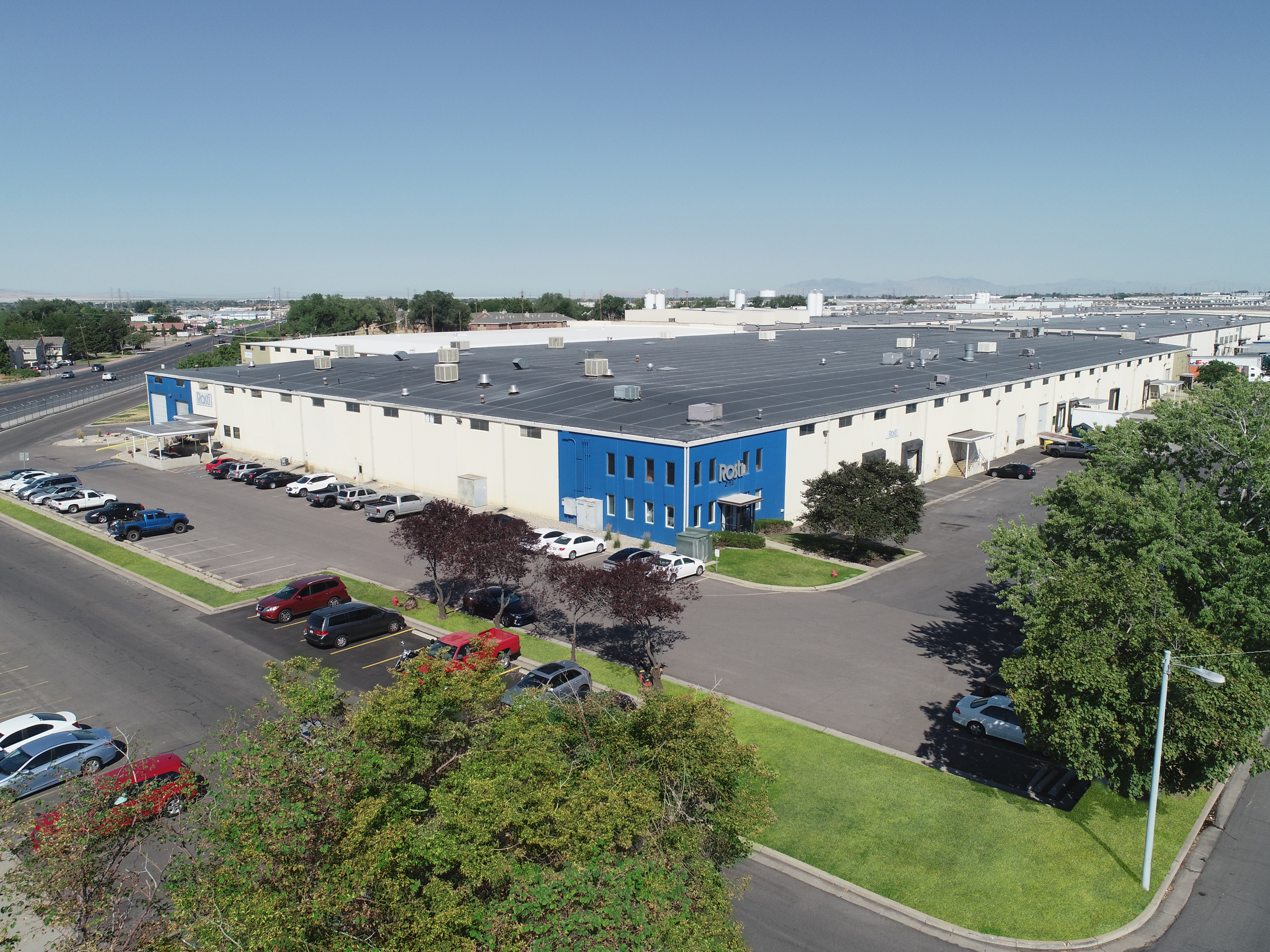
Rosti North America has always been recognized for its superior DFM processes, state-of-the-art facilities and technology, and engineering expertise. Now with Rosti’s global reach and local focus philosophy, customers can rely on collaborative manufacturing expertise and solutions at every step of plastic component development, regardless of location.
Not only do Rosti North America customers have access to digital innovation labs worldwide, a dedicated facility is currently in development at the company’s Germantown, Wisconsin location.
With a global network of resources and suppliers and one of the most dedicated, knowledgeable, and connected teams worldwide, customers will get an expert partner from design through the entire production cycle.
Download this
white paper

Share


Advancements in Producing Production Quality Plastic Prototypes
Download the Advancements in Producing Production Quality Plastic Prototypes Whitepaper

Environmental Sustainability in Plastic Injection Molding
At Rosti, sustainability is more than a policy—it is the foundation of how we design, manufacture, and deliver solutions. As a global injection molder with over 80 years of expertise,…
Read More
Plastic Injection Moulding 101
This guide will walk you through a comprehensive overview of the plastic injection moulding process from design through production – including essential elements of moulding.
Read More
E-mobility Guide
Rosti works with some of the world’s leading producers to face up to the manufacturing challenges in e-mobility. This is a sector with rapid growth – driven by environmental pressures…
Read More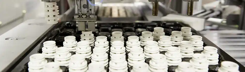
Scientific Molding
It’s not hard to understand how computing and innovation have positively impacted industries of all types over the past 35 plus years. The injection molding industry is no exception. Plastic…
Read More
Metal to Plastic Conversion Guide
This guide will help you understand the metal to plastic conversion process, its benefits, and how to partner with your injection molder to collaborate on all design for manufacturability elements.
Read More
Design for Manufacturing
This guide will help you understand the importance of DFM, and how to partner with your injection molder during the design validation process prior to tooling kick-off.
Read More