Advancements in Creating Production-Quality Plastic Prototypes
Production-quality prototype advancements have made significant progress in recent years.
Powered by technological advancements in 3D printing, optimized tooling for low-volume production, and material science, precision parts can now be designed, produced, and delivered in increasingly shorter time frames. This accelerated process reduces downtime in manufacturing cycles and allows manufacturers to move product development forward and reach the market faster.
Prototyping is a key step in product development that gives companies the chance to perfect their design before launching products to the market. However, in recent years, the methods used to develop prototypes have spanned a wide range. From rapid 3D printing to historically slower methods that require more thorough evaluation and testing of a part’s function and durability, advancements in prototyping technology have made it easier for original equipment manufacturers (OEMs) to validate both part design and production strategy.
Today, new production-quality prototyping technologies are faster and deliver better results when applied in real scenarios. Before we get into the main considerations and process steps, let’s start with the basics.
What is a plastic prototype?
A plastic prototype is a three-dimensional model of a product or item, typically produced using rapid prototyping technologies. It’s used to test a design’s shape, fit, and function before full-scale manufacturing begins. Plastic prototypes are common in industries like automotive, aerospace, plumbing, medical, consumer electronics, and many others.
Prototyping is an essential tool for product manufacturers, as it allows them to evaluate a key component of a physical product prior to full production. Plastic prototypes enable product developers to quickly work with a tangible version of a component—or the entire product—to confirm that the design meets its intent.
This process enables design engineers to make necessary changes before proceeding to the next phase of plastic part production and, ultimately, completing a product that’s ready to launch. In the end, both the manufacturer and the end-user benefit.
Other benefits include:
- Tests design features
- Confirms design intent and a plastic component’s performance in its actual end-use environment
- Provides a benchmark for testing and developing additional features
- Helps identify possible defects and irregularities before full-scale production
- Enables refining for further optimization and improved part efficiency
What are the main differences among plastic prototypes?
Engineers, mechanical designers, model makers, and tooling experts often consider which prototyping approach is best for their plastic parts. With so many prototype advancements over the years, figuring out which type is best for validating a plastic component can be a challenge.
It’s important to understand the benefits and drawbacks of every available method when modifying an existing part or starting a brand new design. By weighing the pros and cons of different plastic prototyping methods and by working with an experienced prototyping partner, you’ll be one step closer to making the right decision.
3-D Printed Plastic Prototypes
Additive manufacturing, or 3-D printing, includes a variety of manufacturing technologies. It’s a cutting-edge approach that’s part of the digital transformation in manufacturing. While “3D printing” is an umbrella term, the three most widely used methods for producing 3-D printed plastic prototypes are:
Fused Deposition Modeling (FDM)
FDM 3-D printing is the most commonly used technique for plastic prototyping, employing an extrusion process that deposits plastic material layer by layer to build the object. Industrial-grade FDM 3D printers can produce plastic prototypes with excellent strength and high resolution. The final properties depend on the materials used, but industrial-grade FDM printers are capable of creating robust, detailed prototypes. This versatile method works with a variety of materials, including PLA, ABS, Nylon, PETG, Polycarbonate, and more.
Stereolithography (SLA)
SLA 3-D printing uses plastic resin to create prototype plastic parts by leveraging a high-powered laser to solidify the model from a vat of resin. An SLA printer uses a light source (such as a laser or projector) to cure liquid resin into hardened plastic. The primary physical differences among SLA 3-D printers are in the design of core components like the light source, build platform, and resin tank. When SLA resins are exposed to certain wavelengths of light, short molecular chains bond, polymerizing monomers and oligomers into solid, rigid, or flexible shapes. This technology is widely used in prototyping, especially in medical, dental, and consumer goods fields.
Selective Laser Sintering (SLS)
Like SLA, SLS technology also uses a high-powered laser. However, the difference lies in the process, as SLS sinters powdered materials together to create the 3-D model. The advantage of this process is the print quality. Prototype plastic parts made with this technique tend to be more functional, with higher resolutions and enhanced durability and flexibility. The most commonly used SLS material is Nylon (PA 11 or PA 12).
What are the pros & cons of traditional methods for 3-D printed plastic prototypes?
Pros:
- Fast production
- Lets you upload CAD files directly to 3-D printer software
- Iterations adjusted within a compressed timeline
- Cost-effective
Cons:
- The part cannot be used for functional testing
- Restricted build size
- The part may be weak and brittle
- Limitations on the types of materials that can be used
- Material shrinkage/contraction cannot be determined with 3D printing
CNC Machining
CNC machining is another relatively fast and cost-effective option for producing functional plastic prototypes, especially if a larger number of prototypes is required (small volume is usually too expensive). This method uses a wide variety of tools with different sizes to carve a 3D model from a solid block of material. CNC machining compares favorably to 3D printing regarding potential for threads and undercuts, tight tolerances, reduced size restrictions, and more surface finish options. Turnaround times for CNC-machined prototypes depend on the model’s complexity and the specific manufacturing services needed.
Materials used in CNC machining technology include, but are not limited to, ABS, PC, PP, POM, PMMA (Acrylic), HDPE, Teflon, and PEEK.
What are the pros & cons of CNC machining plastic prototypes?
Pros:
- Test the fit, form, and function of prototype plastic parts without needing to create injection mold tooling
- Compared to 3D-printed prototypes, offers greater potential for tight tolerances, undercuts, and threads
- Allows for a variety of surface finishes on prototypes, including polishing, painting, powder coating, and more
- Potential for quick turnaround times depending on the complexity of the plastic model
- The prototype will have mechanical properties closer to those of a production-quality injected part
Cons:
- Cost – machining requires large equipment, significant power, and more human oversight than 3D printers
- For parts with complex geometries, CNC machining can be restrictive and may require alternative prototyping methods not limited by cutting tool angles
- Produces more waste material than other methods. Since CNC machining is subtractive, it needs more material than what ends up in the part. The excess is cut away, creating chips that become metal or plastic waste that must be disposed of, unlike additive prototyping
Aluminum Molding Rapid Prototypes
Using aluminum for tooling can be cost-effective for low-volume injection molding. While it is made faster than steel, there are usually limitations when it comes to design features, material choices, and quality.
Aluminum is easy to machine and has a fast cooling rate, lowering cycle times and costs at the OEM level. Part production for rapid prototyping can begin almost immediately once the aluminum mold is finished.
Additionally, compared to 3D printing, rapid injection-molded aluminum prototypes are made with greater accuracy and strength. However, the design and development of these parts may not always match what is needed for production. Because modification options are limited, it could be time-consuming and expensive if a different method is needed. That’s why rapid injection molding is best for early-stage prototypes but could cause issues later if functional production parts are required.
What are the pros & cons of aluminum-molded plastic prototypes?
Pros:
- Steel is a strong conductor of heat, so it heats up and cools down quickly – ideal for injection molding
- Rapid cooling allows more cycles at a time for faster production compared to additive prototypes
- Lower cost tooling investment compared to steel
- Functional testing is possible, but limited
Cons:
- Restrictions on prototypes with unique finishes
- Not as strong as steel, and lifespan depends on molding temperature, number of cycles, and part complexity
- Certain features may be excluded from the part due to process limitations
- Some limitations regarding material types and surface texture
- Limited engineering support
Production Prototypes
Most product manufacturers want a plastic prototype part that can be validated for performance and closely matches the performance characteristics of the intended final production part. If the component is used in product testing before launch, the correct finish for the intended production part should also be applied to the prototype.
Production prototypes made with steel molds are considered pre-production tools that are dimensionally accurate, include all part details, and don’t require de-flashing or other secondary operations. Design changes can be made to the tool for adjustments or optimization. With injection molding, the part should have uniform strength across every angle, and the material structure should remain consistent. Also, finish options for materials are limited in most layered rapid prototyping methods (like 3D printing).
If your part requires a specific finish that benefits its end-use functionality, finish options are greatly expanded and the design won’t be compromised when you choose an injection-molded prototype process.
After prototyping is complete and the design is finalized, the tool is ready for production, saving the time normally needed to start building and qualifying production tools. Historically, lead times for production prototypes have been longer than for other rapid prototyping methods.
Recent advances in technology and tooling processes have enabled product manufacturers to turn their concepts into reality much more quickly. When an advanced injection molding partner uses the latest breakthroughs in 3D printing to achieve time-saving advantages over traditional prototype testing, every part of the prototype process aligns for the most optimal results.
What are the pros & cons of production-quality plastic prototypes?
Pros:
- Allows fast and cost-effective product concept testing without sacrificing quality
- The production mindset is applied throughout the design and development process
- Material shrinkage/contraction can be planned for during design and checked during development
- Largest selection of materials available, including abrasive and filled materials
- Best suited for industries that require thorough testing and certifications, such as medical products
- Protection of intellectual property and the ability to learn from the design and part development process
Cons:
- Production prototypes involve a process and mold that are typically complex and precise—often the last iteration before entering full production
- Very small margin for error
- Often, upfront costs are higher, but the overall value is greater in the long term when you factor in quality, performance, insights gained throughout the process, and speed to high-volume production
Differences in Plastic Prototype Quality
Ultimately, the main difference between a rapid prototype and a production-quality prototype lies in the quality of the mold. Production-quality prototypes are made with steel molds, while rapid prototypes typically use other methods, such as additive 3D printing or aluminum molds.
Using steel in production prototypes and incorporating production mold features into the tooling gives engineers the chance to test the final design and material selection before starting large-scale production. This approach cuts costs and improves efficiency by minimizing the risk of finding flaws after manufacturing millions of parts.
Few technologies have impacted product development as much as 3D printing, rapid prototyping, and production-quality prototyping. Around the globe, organizations are finding new ways to use these technologies to validate product components, ensure end-use functionality, and speed up time to market. As these technologies keep advancing, plastic prototyping will get even more efficient and expand further into industries that may have held back before. The growth of new markets and industries will reshape the role of plastic prototyping and redefine the future of product manufacturing.
When Do OEMs Need Production-Quality Prototypes?
There are several reasons why an OEM might need production-quality plastic prototypes. In many cases, prototypes are used to validate design intent and proof of concept for a component or product before moving to mass production. This helps identify any potential design issues and ensures that the component or product meets all the necessary safety and performance standards.
Below are a few scenarios when an OEM would need a production-quality prototype:
- The product is intended for mass production in large quantities. In this situation, it’s crucial to make sure the design for manufacturing and engineering is optimized so that the product functions as intended with its production materials.
- You need to do consumer research before mass production. You should create production-quality injection-molded prototypes to make them as close as possible to the final product. Producing several hundred injection-molded prototypes allows for very accurate consumer testing and gives you the chance to make changes based on feedback before mass production.
- Your product requires significant testing before hitting the market. In this case, it’s best to test a prototype that is as close as possible to the final component. The materials and production method should be the same, and for complex products, it’s beneficial to mimic the process and fine-tune all procedures.
- Automation and assembly processes for all components should be tested prior to full-scale production. If automation is built to incorrect specifications, feed systems will need adjustment. These systems are expensive and may have to be modified to fit the final specifications of each product component.
- You want to show your resellers/distributors a finished product. Customers might not decide to purchase based only on a sketch or a partially developed idea, so a proven prototype can help demonstrate your product’s viability and solidify sales.
Proof of concept or design is a key factor behind any type of prototyping. Historically, rapid prototyping methods like 3-D printing have helped illustrate what a component or device might look like in terms of size and shape; however, traditional methods often fall short when it comes to proving if a design concept will actually function as intended. Will the planned material withstand all possible environmental factors and conditions? Will the chosen design visually match the product’s aesthetic? Everything from functionality to appearance should be taken into account.
What Are the Steps in Creating a Production-Quality Plastic Prototype?
Developing prototypes through a trial-and-error approach (where you send out a part for prototyping, review it, make changes, and repeat) is risky. The process can be tedious and expensive, and it will likely result in a slower time to market. When skilled engineers or product design consultants are involved every step of the way, they can help reduce material usage, production time, and the costs involved with prototyping and development.
Let’s review the steps for creating a production-quality plastic prototype:
1. Conduct a computer-aided design (CAD) review with a detailed needs analysis.
Think specifically about how you need the plastic component to function. This step is extremely important because if a flawed product design is approved for manufacturing and costly tooling is created, once problems are found, you’re likely to lose money and delay the product’s time to market. Consider these questions during this process:
- Will the part be exposed to extreme temperatures? If so, the material may need to be changed.
- What types of chemicals—if any—will the part be exposed to?
- Will the part be visible, or is it an internal component?
- What does the part need to be? Flexible? Tough? Lubricated?
- Besides temperature, what other elements could the part be exposed to?
- Are there any sealing surfaces on the part?
2. At this stage, design for manufacturing (DFM) protocols should be implemented.
Partnering with an injection molding company that has strong DFM skills is essential to make sure every detail is covered, including gate selection, side actions, cooling needs, critical part characteristics, and more.
3. The CAD review, needs analysis, and thorough DFM work will determine which tooling methods can be used to create the prototype.
Manufacturing engineers use advanced CAD software to choose the right mold for prototyping and ensure it can handle the demands of production.
Some CAD programs, such as Solidworks, offer mold simulation analysis. This technology can identify possible defects, highlight stress points that could cause design failure, and assess how a part will perform under expected pressures. Optimizing component design without a physical prototype lets you move quickly and cost-effectively through the early design stages.
Rapid tooling processes use CAD data and testing results to create molds and tools for short production runs, product evaluation, and full-scale production. These development cycles are much faster and more cost-effective.
4. Tooling for a production-quality prototype can be finished quickly if an injection molding partner has a standardized set of mold bases plus the ability and efficiency to use 3-D printing for metal or steel molds.
Many rapid prototype makers focus on how to make things as fast as possible—while injection molders making production-quality prototypes will often first ask, how will it perform best?
New rapid prototyping methods have been developed that now allow tools to be built from scratch, even in high-temperature resins that withstand regular injection molding conditions. We’ll explore this more below.
How Long Does It Take to Produce a Production-Quality Prototype?
The length of a prototyping process depends on the type of component and its intended use. For instance, applications involving plumbing, appliances, or filtration may require 12 to 16 weeks to test compatibility with water exposure. It’s crucial to understand whether plastic degradation will occur when repeatedly exposed to elements like water. Small engines, lawn and garden equipment, automotive components, and similar products may need material compatibility testing with oil and gas exposure. These factors drive the timeline for creating an injection molded or production-quality prototype.
Ideally, the prototyping process should only take a month or two, and some recent advancements have shortened this timeframe to under 72 hours.
Preparing an initial prototype and CAD drawing for design engineers is an efficient way to move through the process as quickly as possible. This gives engineers a clear understanding of what you expect your component to look like and how you expect it to function.
Here are some approximate plastic prototype development timelines to keep in mind:
| Your Starting Point In The Process | What Will Get You To The Next Phase | Average Timeline |
|---|---|---|
| No design | DFM phase begins where concepts are designed or reverse engineering design is completed | One week to one month, depending on approvals |
| Design complete, but no validation | Engineers utilize mold flow analysis to make component optimizations and create a physical prototype | A few days to a few weeks, depending on the complexity of design |
| Prototype needs further optimization for production | Engineers recreate the prototype using software to improve functionality for production and intended use. Using rapid prototyping or other prototyping methods, a physical model is tested. | Using software and rapid prototyping creates efficiencies that can be completed in days or a few weeks. Traditional prototyping methods take several weeks or a few months to complete. |
| Final prototype is ready to produce | Product design determines type of mold, material, and tooling used based on quantity. Molds are created and the production process begins. | A few days to a few weeks, depending on the complexity of the design, part quantity, and assembly needs. |
In many scenarios, starting from the initial concept through the production process can take months. However, when you work with an experienced injection molder with innovative resources, the process can be significantly condensed. Below, we’ll talk about Rosti’s Innovation Lab, which helps bring concepts to reality in as few as 72 hours.
All OEMs understand that reducing time to market by any amount of time will result in many ROI benefits.
Why Is Prototyping a Critical Role in the Injection Molding Process?
Before assembling a single plastic component—let alone thousands or millions—it’s essential that the engineering and design aspects of the part be carefully reviewed. The design needs to be technically sound, highly functional, and visually aligned with the product.
Today, it’s vital to combine these three key elements while achieving consistent, efficient production. From design to function, OEMs committed to delivering high-quality products should closely evaluate the benefits of using prototypes in injection molding processes.
Prototyping’s Key Functions Include:
Incorporating Scientific Molding Techniques Like Mold Simulations
Rebuilding or adjusting tools is expensive and takes both time and labor. If you move into production with an unproven design, you could face significant challenges. As mentioned above, mold simulations can help reduce risk and should be completed before prototypes are produced.
Reduce Time to Market and Increase ROI
Prototyping is an investment, and it’s rare to get a plastic component right the first time without going through the complete process. Redesigning and making new iterations can be extremely costly.
After building a non-production prototype, you might find minor flaws in the design that could make your end-use product weak, low quality, or ineffective.
If you’ve manufactured hundreds or even thousands of products before discovering mistakes, you know how costly it is to scrap an entire production batch or even initiate a recall. If problems aren’t found before the production run, time and money are lost due to tooling modifications.
What Is DFM’s Role in the Injection Molding Plastic Prototype Process?
DFM plays a critical role in producing production-quality plastic prototypes by ensuring design validation before tooling begins.
DFM (Design for Manufacturability) means designing a product to maximize manufacturing efficiencies for the equipment and/or processes used in production, aiming for the lowest possible unit costs at the highest possible quality. The most important reason to integrate DFM into plastic component manufacturing is that 70% of manufacturing costs are determined by design decisions.
Learn more about how DFM fits into the overall injection molding process in our guide: DFM in Plastic Injection Molding
The Role of Technology in Plastic Prototype Development
Technology is a major factor in DFM when working with an injection molder focused on scientific molding practices. Using mold simulation software like SOLIDWORKS® Plastics Premium, and executing through robotics and process control systems like RJG eDart®, provides predictive insights, process validation, and complete process documentation.
Utilizing and integrating technologies that support the plastic injection molding DFM process requires communication and collaboration between OEMs, design engineers, and molders across many different disciplines.
Another reason to choose a molder that applies DFM principles is the increasing complexity of plastic injection molded parts. Factors like tolerance, draft angles, undercuts, and more need to be considered at the design stage to meet customer quality and cost requirements. Learn more about these design elements below.
What Design Elements Should You Keep Top of Mind During the Plastic Prototype Process?
When starting the DFM process for a production-quality prototype, design standards provide guidance for truly understanding what’s required to successfully mold a part. They also create efficiencies throughout development in several ways. Here are a few design variables to consider, each significantly affecting production time and cost.
Consider Complexity
If your plastic component has many variables that need to be addressed, your prototyping partner should be able to advise on what should or shouldn’t be eliminated. Experienced engineers with both prototyping and production backgrounds can help make these decisions and determine the most efficient project scope.
Avoid Side Actions
During the conceptual design phase (when figuring out the geometry of your part), you may not know if a mold will require a side action. If it does, this added element can impact both completion time and cost.
Not only do side actions increase mold complexity, but they also require time and expertise to function properly. If a part can be designed to avoid side actions while still meeting its intended purpose, this is the best scenario.
Implement Rounded Corners
Adding a radius to avoid sharp corners in prototype design helps distribute stresses and improve the flow of molten resin. During injection molding, hot plastic flows around turns and corners. Rounded corners promote easier flow, while sharp inside corners introduce stress in the mold. This especially occurs during the cooling phase, when the top of the part shrinks and pulls at the corners. Working with a knowledgeable engineer to identify part design improvements will lead to a stronger, more dimensionally stable part that resists warping.
Add draft to your CAD model.
Draft refers to the angles included in your part’s design that help with ejection from the mold. The required amount of draft depends on material thickness and surface texture.
Here are some general draft guidelines to follow:
- Use as much draft as possible: 1-5 degrees on your part
- Draft your part in the direction of pull
- Increase draft for textured surfaces: 2-3 degrees, or 3-5 degrees for deep textures
Eliminate undercuts as much as possible.
An undercut is any reverse-drafted feature that prevents a part from being ejected from a mold and makes tool building more complex. Reducing or removing undercuts will simplify the tooling process. Experienced design engineers can suggest alternative solutions.
Assess the Impact of Material Thickness
Material thickness is one of the most important aspects of part design. It affects performance, appearance, moldability, cost, and more. Thinner walls use less material and reduce cycle time. While minimizing material use is important, getting the ideal wall thickness is a balance between material strength and weight.
| ABS | 0.045 – 0.140 |
| Acetal | 0.030 – 0.120 |
| Acrylic | 0.025 – 0.500 |
| Liquid crystal polymer | 0.030 – 0.120 |
| Long-fiber reinforced plastics | 0.075 – 1.000 |
| Nylon | 0.030 – 0.115 |
| Polycarbonate | 0.040 – 0.150 |
| Polyester | 0.025 – 0.125 |
| Polyethylene | 0.030 – 0.200 |
| Polyphenylene sulfide | 0.020 – 0.180 |
| Polypropylene | 0.025 – 0.150 |
| Polystyrene | 0.035 – 0.150 |
| Polyurethane | 0.080 – 0.750 |
| Rigid PVC | 0.090-0.250 |
| Soft PVC | 0.025-0.150 |
Keep Ribs at 50% of the Adjoining Wall Thickness
In plastic prototype design, ribs add strength, rigidity, and help reduce warping without increasing wall thickness. Ribs should be about 50% of the adjacent wall thickness to avoid sink marks. If strength is especially important for function, using cross-hatched rib patterns can add strength and prevent sink. Thin ribs may be difficult to fill, so designers need to choose materials carefully at the design stage. We’ll discuss material selection further below.
What Are the Best Plastics/Resins for Plastic Prototypes?
Working closely with your injection molding partner to select the best resin early in the DFM and production-quality prototype process is crucial for your part’s successful production.
Material selection affects the strength and flexibility of your molded part. Identifying specific requirements early on helps you avoid costly changes down the road. This is done by understanding key differences among the most commonly used resins.
ABS (acrylonitrile butadiene styrene)
Characteristics:
- Tough with good impact resistance
- Easily machined and meets various aesthetic needs
- Not suitable for parts exposed to high heat
- Affordable price point
Polycarbonates
Characteristics:
- Easy to mold and often increases shatter resistance
- Naturally transparent and ideal for high-strength, glass-like uses (such as safety goggles, medical lab equipment, etc.)
- Not recommended where higher flexibility is needed or for colorful aesthetic options
Glass-filled nylon
Characteristics:
- Thermoplastic reinforced with glass fibers for greater strength and heat resistance
- More electrically non-conductive than many other materials
- Despite a high melting point, it’s more prone to burning than some other materials
Polypropylene
Characteristics:
- Flexible thermoplastic for both industrial and consumer uses
- Highly pliable resin that can be flexed repeatedly without losing its shape
- Resistant to solvents, chemicals, and UV light
Acetal
Characteristics:
- Excellent friction resistance and a very rigid material
- Can be easily colored and dyed during molding
- Doesn’t offer superior heat resistance
Rosti is known for expertise in choosing, sourcing, and molding high heat and specialty resins.
If you want to learn more about the best materials for complex plastic parts, check out Rosti’s High-Temperature Plastic Guide.
How Does Rosti’s Digital Innovation Lab Enable Fast Production Prototype Processing?
Throughout this page, you’ve seen the many aspects of developing production-quality prototypes and the great strides made in technology and part optimization in recent years. Thanks to advancements in 3D printing, optimized tooling for short runs, and materials science, precision parts can now be designed, produced, and delivered in ever-shorter timeframes. Rosti is dedicated to speeding up this process so manufacturers can minimize downtime and accelerate product development to get to market faster.
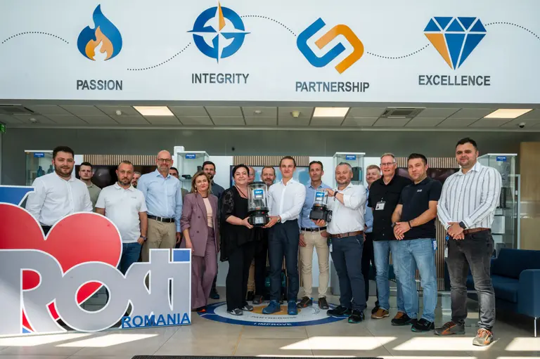
Rosti is so dedicated to this process and the value it provides its customers, it has invested over $1.3M in a new innovation lab at its China location in Asia, and has recently made a second $1.3M investment to launch a new innovation lab in Europe.
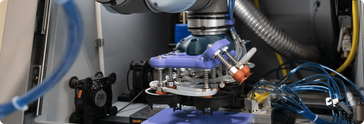
Here’s how Rosti’s Digital Innovation Lab achieves a 72-hour concept-to-reality process:
- Rosti’s engineers receive 3D product data and specifications from a customer, and the clock begins. Requirements are analyzed and optimizations are recommended to improve efficiency and lower production costs. Component prototyping begins right away.
- The Rosti team draws on best practices and a deep knowledge base from previous projects while developing digital simulations. These digital simulations help not only with component design but also with optimizing molding conditions, including gating, cooling, distortion, and cycle times.
- Printing of tool cavities and cores begins. Tools are grown from the ground up using high-temperature resins that withstand standard molding environments.
- Molded parts are verified with optical laser scanning. Full metrology reports are provided within minutes to confirm production intent and support predictive analyses and product measurements.
Within three days of uploading a design, a customer’s idea becomes reality, true to the intended design.
How Will North American Customers Benefit from the Rosti Digital Innovation Lab?
Rosti North America has a reputation for outstanding DFM processes, advanced facilities and technology, and engineering expertise. Now, with Rosti’s global reach and local focus approach, customers can count on collaborative manufacturing expertise and solutions at every stage of plastic component development, wherever they are located.
Not only do Rosti North America customers have access to digital innovation labs worldwide, but a dedicated facility is also currently being developed at the company’s Germantown, Wisconsin location.
With a global network of resources and suppliers, and one of the most dedicated, knowledgeable, and connected teams in the world, customers will have an expert partner from design all the way through the entire production cycle.
Download the Advancements in Producing Production Quality Plastic Prototypes Whitepaper